The Bronica ETR series were 6×4.5 film SLR medium format cameras manufactured by Zenza Bronica in Japan from 1976 to 2004. The series consisted of the original ETR (January 1976), the ETRC (October 1977), the ETRS (January 1979), the ETR-C (January 1979), modified ETRS (July 1982), and the ETRSi (October 1989) (Gonzalez, 2016). Production of the ETRSi ended in December 2004; full technical support for the ETRSi ended seven years later, in December 2011.
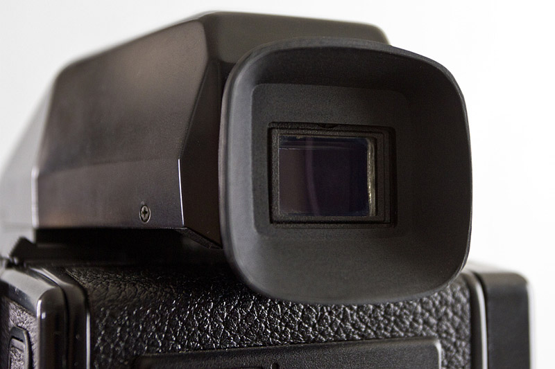
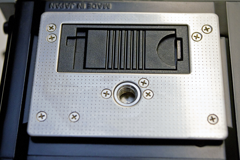
The eyecup in place on a Bronica ETR Prism Finder E.
As noted in a previous post dealing with a replacement battery cover for the ETRSi, it is often the case that parts of such a camera system go missing. Eyecups are another item where replacements are hard to find, and costly when they are found. This occasionally involves buying another prism finder solely for the eyecup. Though that is useful from a long-term repair perspective, it is not entirely feasible if just the eyecup is needed. The intent here was to create a 3D model of a Bronica eyecup, compatible with the Bronica ETR AE-II Prism Finder E and the ETR Prism Finder E. The corresponding original part number is #2720 (BE2720).
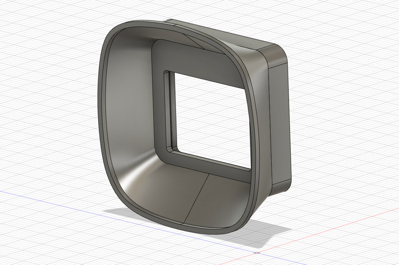
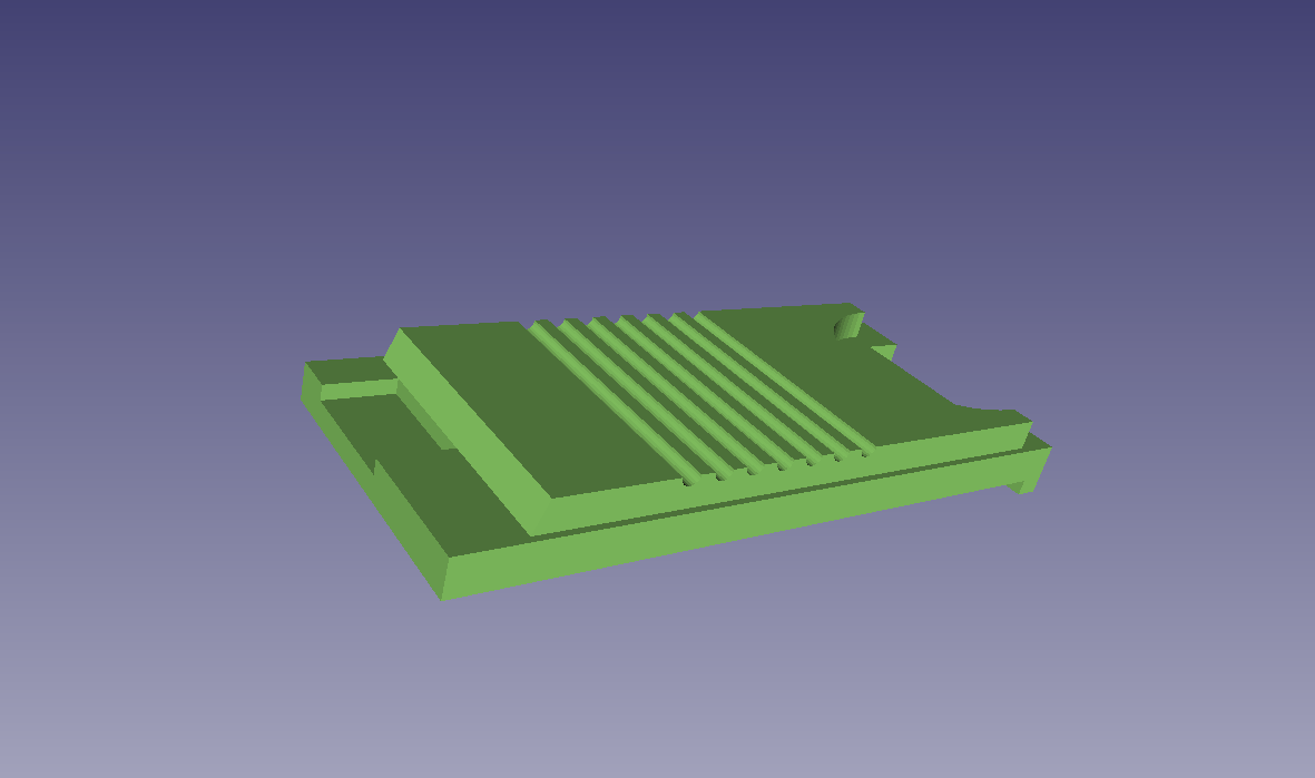
Oblique view of the eyecup in Autodesk Fusion 360.
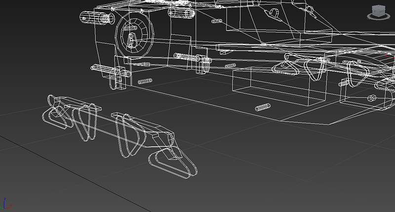
Using the original part as a guide, I constructed a 3D model using Autodesk Fusion 360. I endeavoured to keep it close to the original part in terms of design.
The part was printed on a Formlabs Form 2 SLA (stereolithography) printer using Formlabs Flexible Resin (FLFLGR02). The resin is fairly cost effective at $0.20 USD per ml (Formlabs, 2017).
In PreForm, supports were auto-generated using the following settings:
- Raft Type: Full Raft
- Density: 0.8
- Touchpoint Size: 1.50 mm
- Internal Supports: (unchecked)
- Height Above Raft: 4.00 mm
- Raft Thickness: 1.25 mm
Some touchpoints were manually moved or removed, to make post-processing simpler.
The layer height was 50 microns. The total print volume, including supports and raft, was 3.59 ml. In terms of resin, the cost to print is approximately $0.72 USD ($0.95 CAD; €0.61).
The time required to print was 4 hours and 48 minutes. The time required for washing (in Form Wash) was 10 minutes. Lastly, the part was cured (in Form Cure) for 45 minutes (at 60 degrees Celsius) then, after the supports were removed, cured for another 15 minutes (at 60 degrees Celsius).
While this part was printed using Formlabs Flexible Resin, a Fused Filament Fabrication (FFF) or Fused Deposition Modeling (FDM) printer using thermoplastic elastomer (TPE) or thermoplastic polyurethane (TPU) filament would also produce an adequate result.
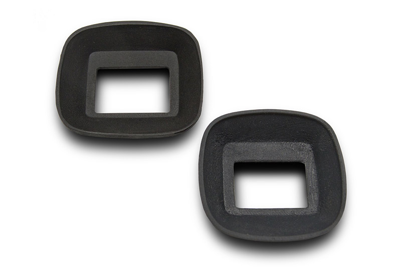
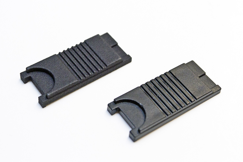
Original (top) and replacement (bottom) eyecup.
Part Download
The part can be downloaded from Thingiverse.
References
Formlabs. (2017). Material data sheet: Flexible. Retrieved from https://formlabs-media.formlabs.com/datasheets/Flexible_Technical.pdf
Gonzalez, D. (2016). Bronica medium format cameras. Retrieved from http://bronica.org/start/bronica-medium-format-cameras.html